Are you working with a hardware device Pfsense or a VM Pfsense? And if virtual are you opposed to having two Pfsense VM’s running within your setup? Or even two hardware devices?
Y-ASK
Are you working with a hardware device Pfsense or a VM Pfsense? And if virtual are you opposed to having two Pfsense VM’s running within your setup? Or even two hardware devices?
Y-ASK
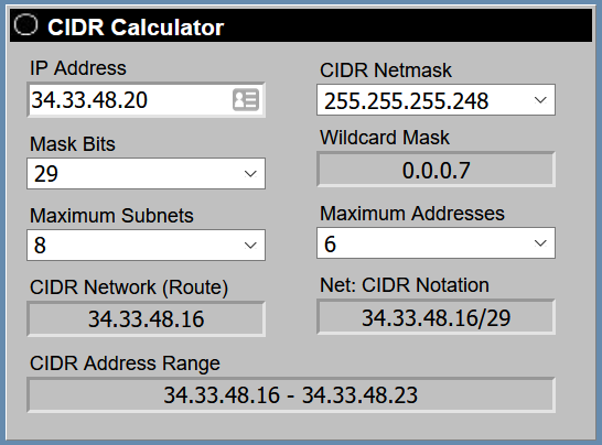
Not really interested in consulting, its for my home-lab, just got into it for quarantine. So i deleted the “gateway” and now have the bridged interface set to my address a .21 and have the router connected to it set up to use address 33.34.48.22 with subnet mask of 255.255.255.248 and the .21 as the router address. I have trouble figuring out how pfsense knows how to route the .21 on the bridged interface, do i need NAT rules to do so or will it automatically route it over the WAN?
I find this discussion interesting! On the one side you have @brwainer who clearly understands networking, routing, and the finer points of the trade and on the other side you have @cashew who is clearly a novice at networking but is willing to learn. And me in the middle who is not exactly an expert but I know enough. And the one thing I do know is that @brwainer is the kind of guy who will throw out his complicated solution and then tell you to go figure it out. Why would you tell @cashew that the answer to his problem is to “bridge” his way through it? Who does bridging any more and if they do, they know what they are doing. I had to go look it up and figure it out myself. It is not a common solution! And as far as bridging is concerned, once you have your bridge in place how are you going to NAT everything to use 33.34.48.25 from the private IP subnet? Are you going to add more network interfaces that will also be “bridged” and then you have to “hairpin” to make it work because everything has to be on one box? Now @cashew is talking about adding another router to the problem at hand. And to show that he is clearly lost he adds “I have trouble figuring out how pfsense knows how to route the .21 on the bridged interface, do I need NAT rules to do so or will it automatically route it over the WAN?” So Bruce, I know you are a smart guy, but don’t you think it might be time to “uncomplicate” the solution? @cashew - I would be willing to help, because let’s face it, I’m somewhat retired and have nothing better to do, but I won’t try to make Bruce’s solution work. That’s a rabbit hole and not one I’m willing to go down… And it doesn’t sound like he wants to go down it either. 
I don’t think the solution that he gave is very complicated, I understand how networking works, i’m just at a loss since i’m very new to the pfsense interface, I really appreciate you offering your help. A bridged interface is like connecting two things together allowing you to give them settings globally as if they were one interface.
Ok, I’m out and I wish you the best. Feel free to PM me if you would like to discuss other options.
Y-ASK
@cashew asked for two physical interfaces on the router, igb2 and igb3, to have client devices in the same subnet. A router should only have a specific subnet on a single interface, things behave poorly otherwise. So we need a virtual interface that is able to combine multiple physical interfaces - that is called a bridge. The only alternative method is to move the client device’s physical ports onto a switch, and then the router’s single interface for the subnet can be the physical port which connects to the switch. In the end these two methods end up almost the same, especially because a switch is just a bridge implemented in hardware (I’m serious - switches were invented as a way to have a bridge [instead of a hub] that didn’t rely on slow software running on a comparatively expensive general purpose CPU). Look at these two diagrams - you’ll see that the switch just moves into the router and is called a bridge, and in both cases the subnet is only present on a single interface on the router. I used “LAN” and 192.168.1.x, but the same applies when you have a subnet of public IP addresses.
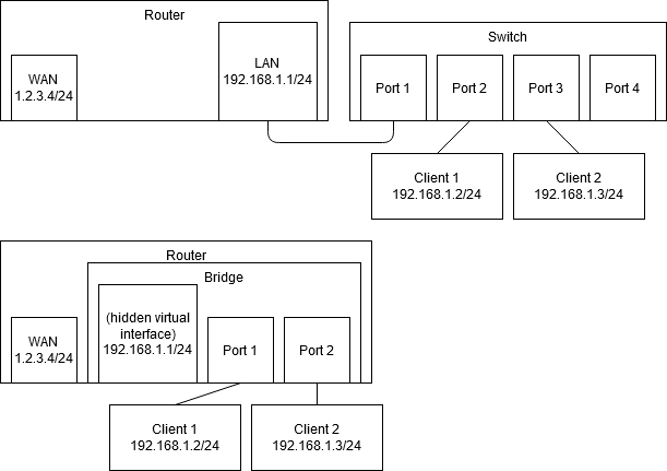
As for whether bridges are common or not, I can assure you that they happen fairly often in business/enterprise. Also in every SOHO router (all in one routers with wireless), the “LAN” interface is really a bridge, of which the ethernet ports and the wireless interface(s) are members. Lawrence Systems has even made some videos using them:
https://www.youtube.com/watch?v=1EXgyvwJZ6k (bridge for transparent firewall and IPS)
https://www.youtube.com/watch?v=8MPDV1Iqu88 (practical demo of the above)
https://www.youtube.com/watch?v=xE-vDKOxSrc (bridge for LAN to combine ethernet and wireless)
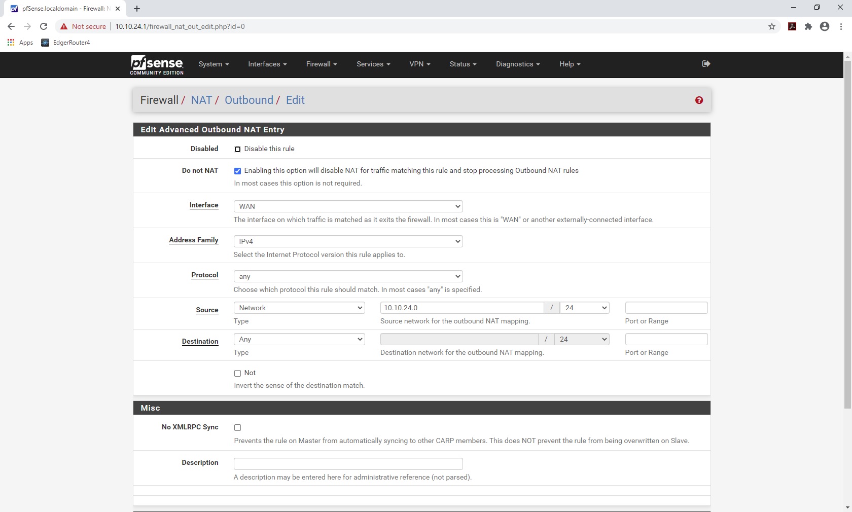
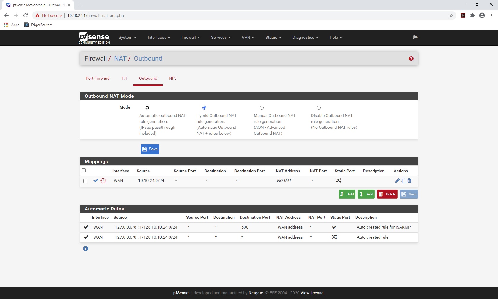
I partially addressed this in an earlier reply. Once the bridge is set up, 33.34.48.25 can be added to it as a Virtual IP. This is done under the section Firewall > Virtual IP. A virtual IP allows you to add a second IP, in the same subnet or a different subnet, to an interface. Therefore the bridge interface would have both .21 and .25 on it. Once that is done, in the section Firewall > NAT > Outbound you can create a rule that specifies anything from the private subnet should be NAT’d to the .25 IP. At this point, I believe the routing should work as desired, but I have not actually set up this exact situation. Usually the private subnet is NAT’d to either the primary WAN IP (the one which AT&T provides via DHCP) or the first IP in the /29, which is already on the bridge interface. Or a separate router is being used, as is the case for the lab router.
There are always many paths to achieve a solution. When looking at the problem/request in this case, the solution I’ve presented thus far seems the best to me. From a networking principles perspective, it is fairly neat and clean. The complicating factors are that the multiple clients in the /29 are desired to be directly connected to the router, not via a switch, and that they want to NAT a subnet to an IP within the /29 directly from the primary router. The solution could be much simpler and straightforward without these requests. My job as an enterprise engineer is to make the requests happen unless there is an overwhelming reason to do otherwise, and in this case the required complexity is not overwhelming (I don’t mean this as in “I don’t think it is overwhelming”, more along the lines of “a moderately experienced and trained routing/switching engineer can understand and execute this solution”, and I am trying to provide guidance towards the key points required to get it done without writing out a step by step guide.
@cashew If you are having trouble getting this done, I suggest breaking it into phases:
Phase 1: the servers and lab router are connected to a switch, and this switch is plugged into a port on the router. Configure the .21/29 IP onto the port, don’t use a bridge. The goal of this phase is to have at least one of the servers, or the lab router, able to access the internet and also be reached from the internet. The one thing I don’t think I’ve mentioned thus far is that under Firewall > NAT > Outbound, you may need to make changes so that the traffic from the /29 IPs does not have NAT applied to it. The easiest way is to change it to “Manual Outbound NAT Generation” and then delete the two rules that apply to the /29 network. Note this means that any new networks you add to the router will not automatically be NAT’d when going to the internet.
Phase 2: Delete the interface with the /29, and recreate it as a bridge including the ports you want for the clients. The goal here is for all of them to work
Phase 3: Add the virtual IP to the bridge, and add the outbound NAT rule for the traffic to use it (also check whether there is a conflicting rule that was created before).
I’ll continue helping you out. The main reason I don’t want to make step by step instructions is I would want to test them out and be sure they fulfill the goal, and that’s an investment beyond just responding in a forum based on the knowledge I have already.
Yeah I wouldn’t care if you tested it or no, Exactly what you did is what I wanted. My frustration was that I know exactly what I want to do, just don’t know how and the interface is new to me. Testing it was way beyond what I was asking for, sorry if something wasn’t getting across successfully.
Hey Bruce, Great response!
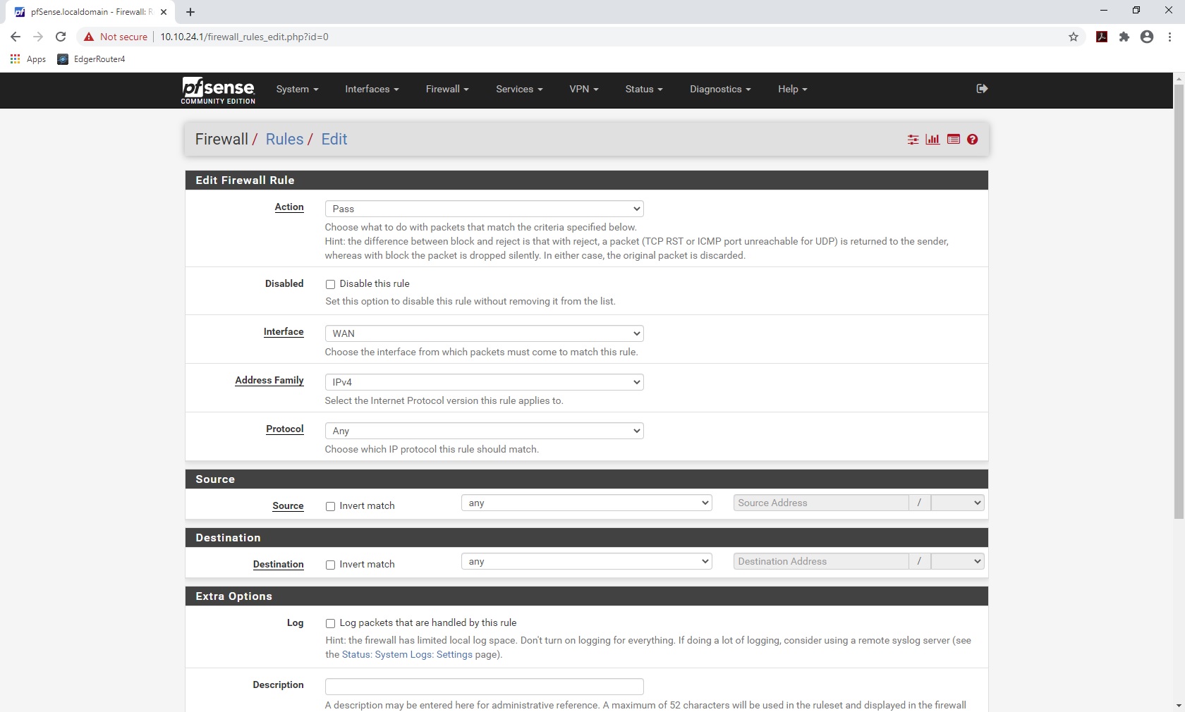
What follows is something that @cashew asked me to research for him earlier in a PM. Here’s what you need to do to allow Pfsense to act as a router. Be careful because this leaves everything wide open. You should play with this and make sure you can get traffic flowing then slowly lock down what you want to restrict. The system is a newly installed version of Pfsense with all of the default settings. As the document that you linked states you need to disable NAT and then allow traffic through the firewall. The first two pics show disabling NAT. The last is the firewall rule on the WAN interface. You will need to change the IP addresses to your config.
Y-ASK
The way I tested this was to have two workstations on either side of the PFsense box. I captured packets on the WAN side while pinging on the LAN side to the WAN side workstation and verified that the “From” IP address was the internal LAN IP address of the workstation. I then set the WAN workstation to use the WAN IP address on the Pfsense box as the gateway for the workstation station. I then pinged the internal workstation and the traffic was passed successfully. Get this working first then move on to bridging and setting the virtual IP.
The source for the firewall rule would be the public address right?
The source for the Firewall rule is “Any”. The source for the NAT rule is “Network” and the network is 34.33.48.20/29.
Remember that the WAN interface gets the DHCP assigned IP from your ISP and then you apply the IP block network to the LAN interface. You’ve got to make sure that you put the specific IP address on the LAN side when asked (34.33.48.21) and also the specific network block (IE 34.33.48.20/29) when required. This is for your interface setup, not the Firewall rule and NAT rule we are talking about above. You have to read carefully what is being asked for.
Your points and instructions are good. You’re right that in order to use public IPs “publicly”, a firewall rule has to be made to allow that. That’s why I said before that there was no security risk in bridging the interfaces together, because the hosts need to be secured against direct internet connections, but I did forget that on PFSense you need to explicitly allow through the firewall for inbound connections to that subnet. I blame working with too many different router/firewall types!
Paying attention to what each field on the different forms is asking for is definitely the hard part of doing complex networking. Knowing what form is going to do and how the pieces of data work together helps but its always easy to make dumb mistakes like putting in the wrong subnet mask and then have a hard time figuring out why half the subnet works and half doesn’t.
And I need to add a WAN IP alias too, right? Or am I just passing it through the NAT? and where do I put this in? and also the specific network block (IE 34.33.48.20/29) when required. This is for your interface setup, not the Firewall rule and NAT rule we are talking about above. You have to read carefully what is being asked for.
Using an alias helps so you don’t accidentally mistype it somewhere, although PFSense mainly only uses aliases in the firewall rules (some other firewall systems use Objects for everything - an alias in PFSense is a simplified object)
Modifying the NAT rule so it doesn’t mess with your static IP block is one example where PFSense doesn’t (as far as I know) use aliases.
I think the part you quoted was just calling attention to the fact that in some places you need to put in the firewall’s own IP (.21 or .21/29) and in other places you need to put in the network itself (.20/29).
Yep, what Bruce said…
Y-ASK
Still not workie work added the nat exclude rule, added the firewall rule for the wan, and added a rule on the lan port and a ip alias. This is still my confusion “Still need some more help with it, really still confused on how to get a port other than the default LAN to use the public IPs from the WAN. Like what firewall rules would do such a thing.”
So what is or is not working right now?
Ping from router to a public IP block client (.22)?
Ping from public IP block client to router (.21)?
Ping from public IP block client to various internet IPs?
Ping from an outside device to the router (.21)?
Ping from an outside device to a public IP client (.22)?
When one of these fails, is there any entries in the firewall log on PFSense? May also want to enable logging for the rules you’ve added to confirm they are working as intended.
Googling “what is my IP” from clients connected to various places (lab router, private LAN, etc) to confirm NAT works (or doesn’t make a change) as intended?
How will you know when things are working? What specifically are you looking for?
Ping from the router behind the pfsense (the lab router) to any outside ip
and the clients on it can’t ping either, but the clients using the DHCP address from at&t work fine. So the pfsense does have internet
I’ve gone back to your original diagram and noticed a few problems:
Yeah I was using the wrong example address I meant 99.133.254.40/29 I didn’t properly calculate the example address I gave you. My bad.
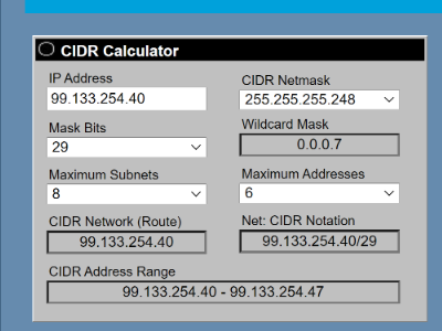
OK. so let’s assume that the IPs are assigned as such:
99.133.254.41 (first IP): PFSense interface IP
99.133.254.42 (second IP): Lab Router
99.133.254.43: Server
99.133.254.44: Server
99.133.254.45: Server
99.133.254.46 (last IP): Will hopefully have private LAN on PFSense NAT’d here
Please answer each of these questions, using the IPs above.
Can you ping from PFSense to the lab router?
Can you ping from the lab router to PFSense?
Can you ping from the lab router to various internet IPs?
If not, please provide a traceroute to the IPs you tried.
Ping from an outside device to the PFSense? (Outside device means from a friends or relatives house, or your phone with wifi disabled)
If not, please provide a traceroute.
Ping from an outside device to the lab router?
If not, please provide a traceroute.
When any of these fails, is there any entries in the firewall log on PFSense, and/or the lab router? You may need to modify firewall rules to enable logging.