I’m running pfSense 21.05.1 on both firewalls with wireguard package version 0.1.3.1
I’m completely new to wireguard and have been trying to decipher the wireguard documentation and both Tom’s and Christian McDonald’s videos. There’s just enough changed in the current versions of everything that I’m getting stumped.
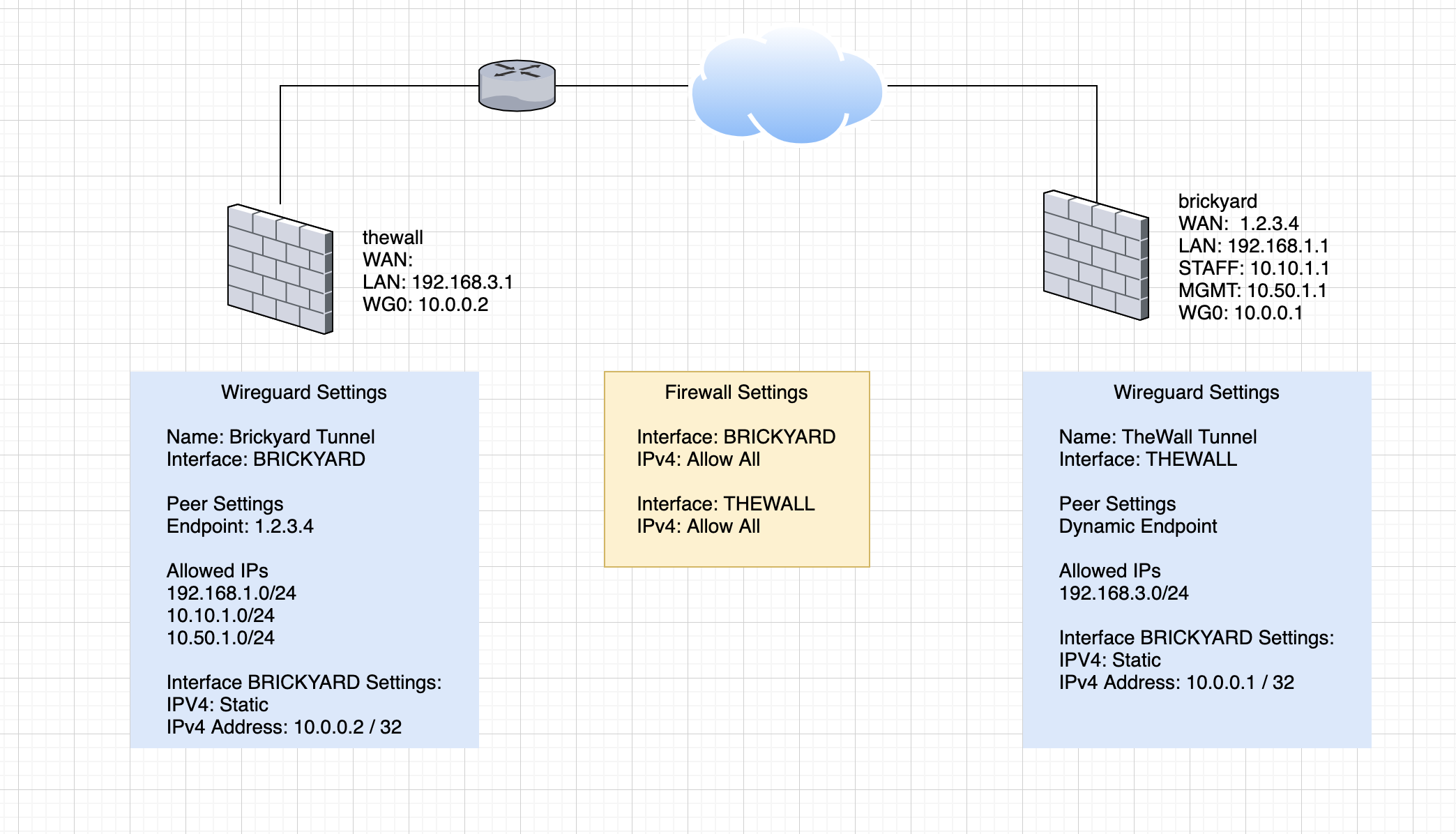
So here’s what I’ve currently got setup:
When I check the status of the peers in the Wireguard interface, it’s showing successful active handshakes. However, traffic is not being routed between the two interfaces.
Christian has a pretty detailed video regarding failover using two wireguard connections, which I used to give me the tip to put the interface address in. This is different than Tom’s videos which were with an older version of the package which didn’t yet separate out the interface address from the wireguard setup.
Also, Tom never setup gateways or routing, but Christian does. I think this is likely only needed because he’s routing internet traffic through it, but I’m not 100% sure. I’ve tried both ways, but neither worked.
Hopefully, my mistake will be obvious in the diagram. Assistance is appreciated!
If you’re trying to route through it… what does the routing table of each firewall look like?
I haven’t defined any specific routing. Tom didn’t specify any routing in his demos, so I was under the assumption that it wouldn’t be necessary – especially when the allowed IPs were explicitly defined in the peer table. Those IP ranges aren’t in the respective firewalls, so I assumed that pfSense would know to route through that peer.
I’ve honestly never had to configure routing for any of my networks, so I’m not sure where to start here.
I wasn’t asking for what routing you had set up. I am asking for the “Routing Table” - meaning the live data that the router will actually use to decide where packets should go. I believe that setting the peer IP ranges in WireGuard should enter those into the routing table, but you have to check yourself to be sure.
In PFSense, go to Diagnostics > Routes. This is the routing table. Copy the “IPv4” table from both of the devices and paste them here. The “Preformatted Text” (</> button) may help.
Like this:
Destination			Gateway			Flags	Use		Mtu		Netif	Expire
default				192.168.13.1	UGS		3754	1500	vtnet0
127.0.0.1			link#7			UH		82		16384	lo0
192.168.13.0/24		link#1			U		220834	1500	vtnet0
192.168.13.101		link#1			UHS		0		16384	lo0
192.168.254.0/26	link#2			U		0		1500	vtnet1
192.168.254.1		link#2			UHS		0		16384	lo0
192.168.254.64/26	link#3			U		0		1500	vtnet2
192.168.254.65		link#3			UHS		0		16384	lo0
192.168.254.128/26	link#4			U		0		1500	vtnet3
192.168.254.129		link#4			UHS		0		16384	lo0
192.168.254.192/26	link#5			U		0		1500	vtnet4
192.168.254.193		link#5			UHS		0		16384	lo0
The “Use” column will tell you how often each of those routes has been used. I don’t remember whether that is in sessions, or packets.
Oh, ok. I’ve masked the public IP, but everything else is as-is. The pfSense on this end is an SG-1100, which is why the netif may look a little strange compared to your example. The remote end is a netgate 7100, which has equally as confusing Netif entries. 
IPv4 Routes
Destination      Gateway	    Flags	Use	    Mtu	    Netif	      Expire
default	         --.--.---.-	UGS	    365614	1500	mvneta0.4090
10.0.0.2	     link#16	    UHS	    0	    16384	lo0
10.0.0.2/32	     link#16	    U	    0	    1500	tun_wg0
10.5.20.0/24	 link#13	    U	    0	    1500	mvneta0.20
10.5.20.1	     link#13	    UHS	    0	    16384	lo0
10.5.30.0/24	 link#15	    U	    0	    1500	mvneta0.30
10.5.30.1	     link#15	    UHS	    0	    16384	lo0
10.5.31.0/24	 link#14	    U	    0	    1500	mvneta0.31
10.5.31.1	     link#14	    UHS	    0	    16384	lo0
--.--.---.-/24	 link#12	    U	    203774	1500	mvneta0.4090
--.--.---.---	 link#12	    UHS	    0	    16384	lo0
127.0.0.1	     link#6	        UH	    346	    16384	lo0
192.168.3.0/24	 link#10	    U	    1226207 1500	mvneta0.4091
192.168.3.1	     link#10	    UHS	    0	    16384	lo0
Sorry to take so long, was too busy to come to forums.
So if the routes were installed properly, you would have something like:
Destination: 192.168.1.0/24
Gateway: 10.0.0.1
You are also missing a route for 10.0.0.0/24 - notice how the rest of the subnets on the router are fully listed?
I have no experience with WireGuard on PFSense. I don’t know what the right config is or what you are missing. But at the end of the day, the routes have to get in this table. Wireguard is presented as a direct ethernet cable to the other end.
EDIT: I haven’t looked at the sources you’re referencing, but are you sure the wireguard interface IPs should be /32s? I would try changing those to /24.
According to all of the documentation that I have, Wireguard automatically creates the routing tables when subnets are explicitly defined, such as what I have here. If I had used a global mask (i.e. 0.0.0.0/0), then the routes would not be created and I’d need to manually create them myself. I don’t even know where to begin with that, as I’ve never had to do it on pfSense.
As for the /32, that’s what I’ve seen both Tom and Christian do when they were setting up their connections. I’m not 100% sure I understand why, but I would have thought I should be using a /24, as well. I’d love for someone with some Wireguard experience to chime in and help me understand it better. I love the possibilities here, but I’ve got no clue as to why it’s so hard for me to figure out!!!
I’m going to destroy my tunnels and recreate them with /24 and see if that does anything.
I’ve also got a ton of questions around where the interface IP goes after you create the tunnel. In the original wireguard implementation, if you added an IP address, it added it into the interface as the address there. However, it does not appear that it works that way now, and once you’ve created the tunnel, there’s no way to modify this. Christian doesn’t even use a wireguard IP address in his failover video, but that’s because he manually creates all of the gateways and routing manually. I just want the default wireguard implementation, which supposedly does this automatically, so I’ve not used his technique.
I agree with your routing table assumptions, too. I’d expect something for 10.0.0.0, 192.168.1.0 and 10.10.1.0.
I’ll post back once I’ve had a chance to try the tunnel recreation with a /24.
I recreated the tunnels with /24 and it still didn’t work. Looking at the route table, I’m not seeing the additions.
The PFSense forum may have more people with experience and knowledge of this specifically.
After spending several hours on the netgate forums, I found a comment someone had posted that the package did not automatically create the routing, which is what I believe we had decided here. I recreated the tunnels and manually added the routing to go through manually defined gateways for each end, and everything worked. I found that 0.1.3_1 was somewhat inconsistent in creating the connection, but at the same time, I noticed that 0.1.5 had become available this morning. Upon upgrading to it, I’ve not had any further issues.
Thanks Bruce for pointing me to the netgate forums. I’ve learned a LOT about routing and gateways over the past few days. I think I understood the concepts pretty well going into it, but the automatic nature of today’s software had hidden the implementation from me where I didn’t actually have to do anything in the past. All-in-all, it was a relatively painless effort to get it going. I may have to update my network diagram and post here for those who might be trying to do a site-to-site wireguard vpn with the current package.
1 Like
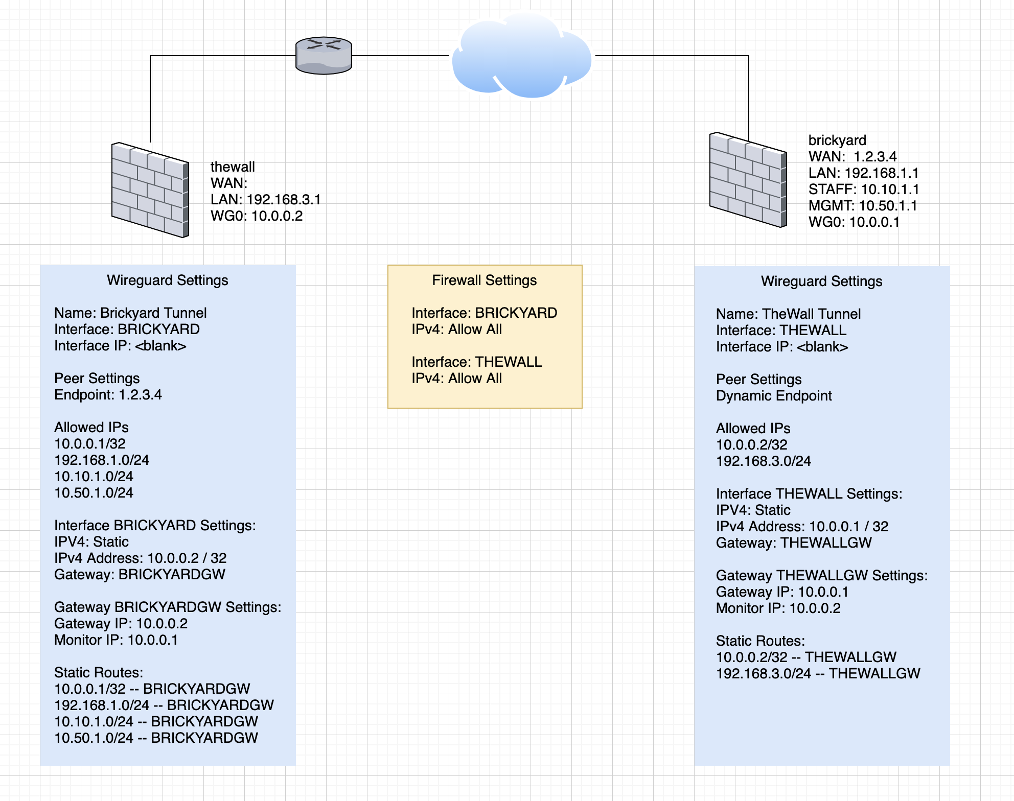
For the sake of closure on this thread, here is the final configuration I ended up using for a working site-to-site VPN.
OP, don’t forget that Wireguard connections are seen as interfaces after they are up. You need to setup rules to allow/deny whatever traffic you want on those new interfaces - just like any other physical interfaces on your firewall. Same concept as for VPN tunnels and interfaces.
They were set up. That’s the yellow box in the middle – the rules for each interface. The missing item was manually defining the routes and establishing custom gateways. That’s what I was trying to clarify in my last diagram.