can anyone provide a link or guide me how to get virtualized pfsense setup?
i’ve got an HPE Proliant DL360p Gen8 server running proxmox, with a pfsense vm up and running, but im at a complete loss on how to set up the physical hardware to get everything running. i originally assumed i would be able to connect to the webgui and upload a backup of my original box, then unplug the box and run straight through the virtual pfsense, but once i setup wan and lan in the console and try going to the webgui address the site dies. can connect fine through console, just no webgui.
current setup is modem>pfsense>unifi 24 port poe switch>unifi 24 port non poe switch, U6LR AP, NanoHD AP, pc, server, etc…
i cant find any guides to show how to do this with unifi switches. the closest one i’ve found is here with a tplink switch and vlans (not sure if this is even the correct way to do it).
i started going through this guide and setting it up the best i could translating everything hes doing on tplink to my unifi switch, but i’ve spent so much time trying to troubleshoot issues with this server and finally getting the virtualized pci working on it (that was a huge ordeal), that instead of potentially wasting more time on doing the wrong process or if there is a better process, id come here and ask the pro’s.
one other guide i found just said to plug the modem into the switch and setup that way, but that cuts out all my internet since everything is already setup through my previous pfsense.
its probably something simple that im not doing, but please, any guidance on this is greatly appreciated.
I run pfSense virtualized and have run it a few different ways in the various iterations of my homelab setup. The first way that I did it was to connect an ethernet cable from my modem to my ProxmoxVE server (we will call this WAN) and then another from my ProxmoxVE server to my main switch (we will call this LAN). I also connected another cable from my ProxmoxVE server to my switch as well (let’s call this one MGMT). This allowed me to configure the MGMT interface for ProxmoxVE during the ProxmoxVE install and then after using the web interface configure the WAN and LAN connections on their own Linux bridges. I then assigned them to pfSense by adding two network interfaces and selecting the appropriate bridges. Then when configuring pfSense it was as if it was “physically” connected to the pfSense machine.
Now I run things a little differently and have my WAN and LAN connection set on separate VLANS as well as the Proxmox management interface on another VLAN. This allows me to bond all the NICs in the machine using LACP into three categories management, storage and virtual machines. pfSense still gets multiple interfaces (WAN & LAN) but now is able to access the WAN and LAN via VLAN tag on the interface added to the VM so it can be accessed no matter what node I run the pfSense VM on. I changed because I went from 1 dedicated pfSense node to adding it into my ProxmoxVE cluster which is now up to 7 nodes.
so the vlan route is the better way to go then?
k im just trying to figure out how to do this. it just dawned on me that my modem is in bridge mode. so im going to take it out of bridge mode and reset my network to see if i can get it to connect that way.
my server has a dual 10g sfp+ nic. ive got an rj45 to sfp+ adapter to run off my modem. would it be better to plug that into the switch, then have an sfp+ cable going from the server to the switch? or plug into server then second plug to switch?
It really depends on your setup and if you have more than one node and want to migrate your VM around and your switches capacity as you will be moving a lot more traffic through the switch if your LAN and WAN are using VLANs.
If your modem is 10g then yes you want to use a 10g connection but if it is only 1g then you are better to connect your 10g connections to other 10g capable devices in your setup IE: your switch.
my modem is 2.5g. i’ve got 2 switches (unifi 24 port poe w/ 2x sfp+ and unifi 24 port non-poe w/ 2x sfp+)
id like pfsense and my pc to run off the 10g ports since they are the only 2 things i currently have that can take advantage of the higher output.
i have lots of switch space available. i just dont know how to actually set up the vlans and which rules i will need to get it going the way you say.
im currently in a setup loop changing from ip address groups. original pfsense was 192.168.x.x. modem was 68.154.x.x. last night my ISP did some weird shit and i had to reset my modem, which gave it a new ip in a 10.0.x.x range. so when i install proxmox it puts me in a 10.0.x.x address pool, then i install pfsense and change the lan ip back to 192.168.x.x and disconnects me, which means having to reinstall proxmox to get the updated ip address since apparently there is no other simpler way to change the ip of the server than that.
i do have another node that i’ve got set up that im hoping transferring my pfsense vm to while i update the main server, then back again will work. its a huge pain in the ass and time consuming.
i just want to have my network setup as best as possible. if vlans is the way to go then i will go that route. just need a guide on what i need to do that
You could connect your modem (in bridged mode) using the 10g port to the non-POE switch which will become your MAIN switch and I would connect your Proxmox node to the switch as well using 10g (this will be your WAN connection using a VLAN) then we can use another VLAN on the same 10g port to connect your LAN (again using a VLAN) which will also be the same VLAN for the rest of your network that is on the LAN side. I would connect your Proxmox administration interface to the MAIN switch using a 1g connection and make sure it is on the LAN side of things. Now you can use your POE switch connected to the other switch using 10g to provide POE ports for say cameras or wifi devices as well as more ports on the LAN VLAN.
Without drawing things out its sorta hard to explain how it all interconnects as you have a physical layer, a VLAN/virtual layer and then what I can the logical layer which is how it works when in use where the hardware and virtual side are sorta removed and treated as equal for the sole purpose of seeing how data and the solution will function.
sorry for the late response, had a busy last couple of days.
so i did figure out the ip address situation. i’ve never played with the ISP modem/router before besides putting it into bridge mode. so when they reset my network last week it was giving me a 10.0.x.x address which confused the hell out of me since its always been 192.168.x.x. i found the settings in that modem to change to 192.168.
i get exxtremely confused when i have both switches connected. one will get the proper ip address and the other will get the dns address (68.151.x.x or something along those lines).
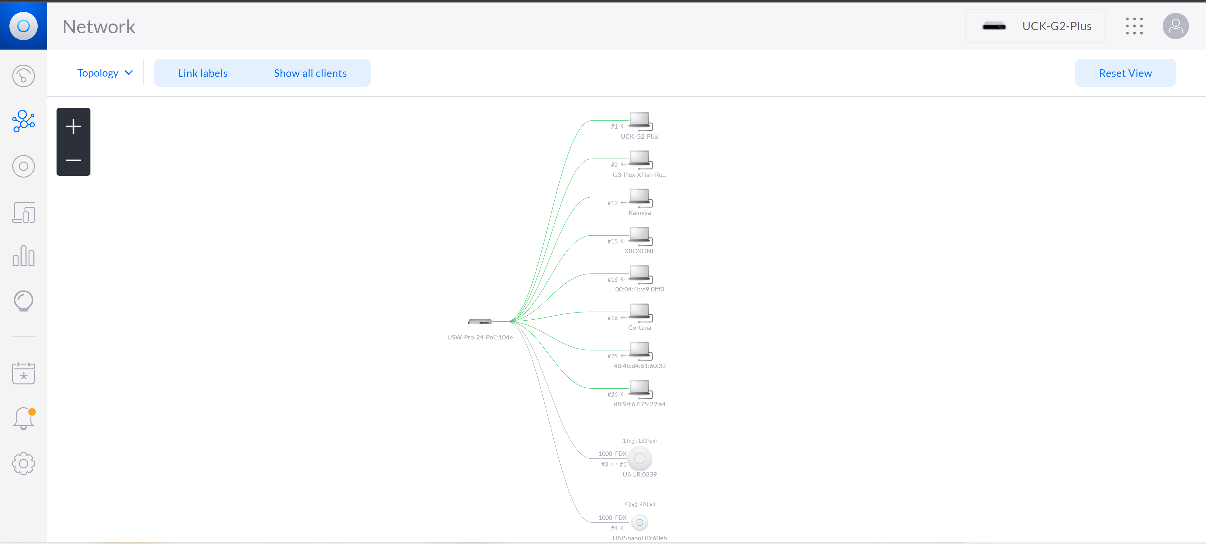
i can try to draw something and post it. do you want a complete network breakdown of the hardware? cause right now its basically isp modem>switch 10g on port 25 (uplink)>server 10g on port 26 (downlink)
in between that theres pc, xbox’s, ap’s, cameras, cloud key gen2+ controller and nvidia shield box.
would it be better to use both switches? i dont neccesarily need a whole lot of open poe ports. really just for the unifi stuff (aps, camera and cloud key). those only take up 4 ports. i maybe add an outdoor ap down the road for my doorbells, but that would put me at 5 poe ports. i think i have 7 ports used for other devices, but that puts me at 12 of 24 1g ports.
the only other sfp+ port i will need for the foreseeable future is for my pc. can i plug the ips modem into the server, then server to switch with sfp+? then have the second port used for the pc?
the way you explained it in your first paragraph uses more sfp+ ports than i have available on 1 switch.
modem>switch 10g + server>switch 10g will use both available 10g ports on the switch, so will not be able to run a 10g link to the other switch
Shouldn’t need the whole network at this point just the modem, switch(es), servers and maybe WAPs. If you only have 2 10g ports on your switches then you could do 10g from the server to the main switch and from your desktop to the second switch and use the other 10g port to link the two switches. I found the best way for me to map things out was to draw out the hardware, then add the layers until I had everything that needed to connect to the main stuff (modems, switches, servers, WAPs, etc.) drawn in.
link 25 and 26 are the 10g links. like i said, i dont have the other switch connected right now cause it was giving me issues with pulling the correct ip