[SOLVED]No internet access on wireless networks with VLANs

EDIT: Sorry, the forum only allowed me to post 1 embedded media per post, so I had to post the additional 3 images as separate posts…
EDIT 2: Received badge to be able to post multiple embedded images, so deleted the other posts and re-embedded the images in original post…

Long time follower of Lawrence Systems on YouTube. I have learnt and configured a lot on my pfSense box using LTS videos. Finally hit a snag which is either not available in any video or I am too thick to understand. So here I am…

I recently got a TP-Link EAP 225 with the hopes of setting up different VLANs for the various networks that I wanted to segregate. I have set up 4 separate SSIDs with different VLAN ids but I don’t get internet access on any of them. I have a 5th SSID which has no VLAN id associated and that works just fine. Note that I get the correct IP assigned to the device while on the network, I just am not able to access the internet. I can also ping the X.X.X.1 (which is the gateway IP for the VLAN that I am connected to via that SSID)

My network structure is simple:

modem → pfSense on bare-metal → switch → AP

  1. Trunk – Switch Port 45 carries LAN, WORK & GUEST networks from pfsense to switch
  2. Trunk – Switch port 46 carries CCTV & IOT networks from pfsense to switch
  3. Trunk – Switch port 7 carries everything from switch to AP

I have 2 trunks from pfsense to switch because the cameras are chatty and wanted to separate those over different trunks – eventually I may separate the switch and APs too in order to get them completely independent of each other. Also, I had extra ports available in my pfSense network card

Here’s my pfSense configuration for the different VLANs
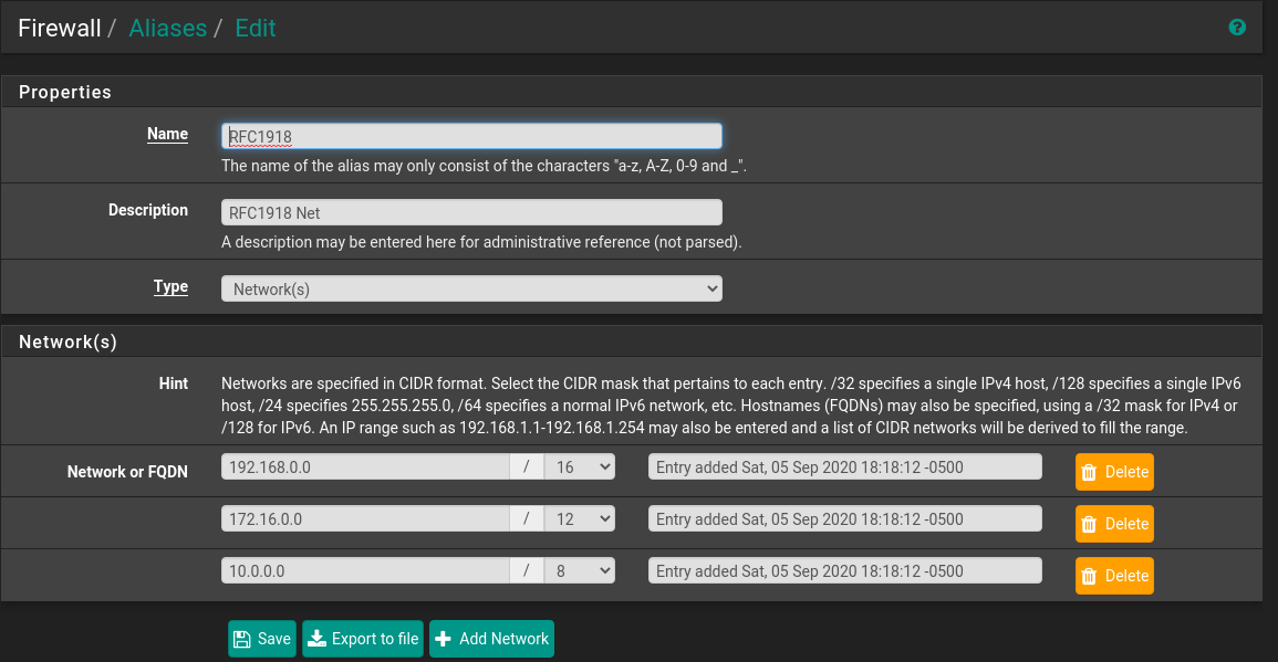
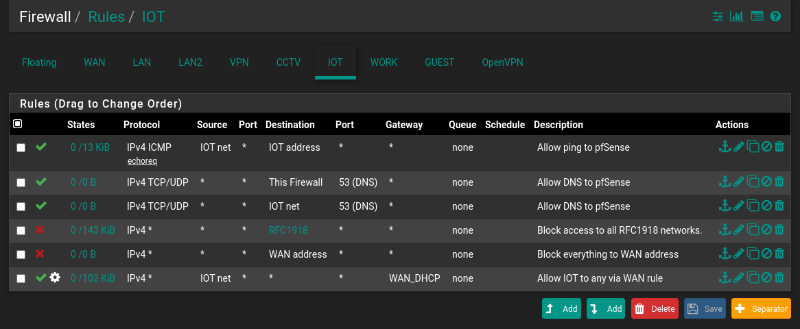
Firewall rules:

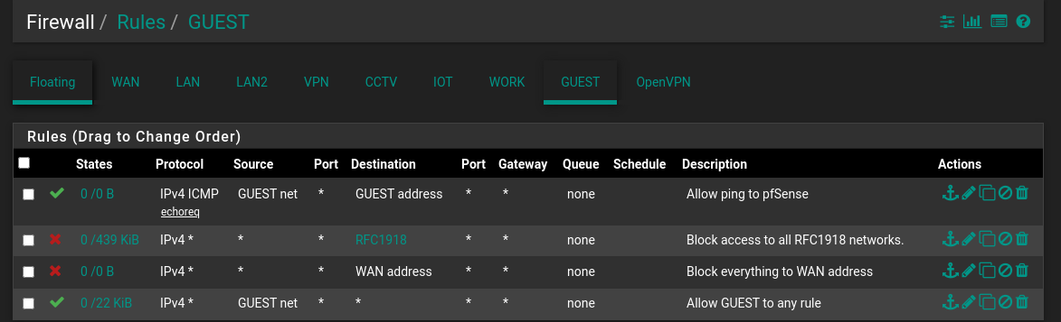
Initially I thought that I might need a allow rule so that the network could access the pfSense for DNS, but even when I added that rule it didn’t make any difference. Here’s a screenshot with the rule added for the IOT network. Still no internet access.

Here’s how my interfaces are assigned:

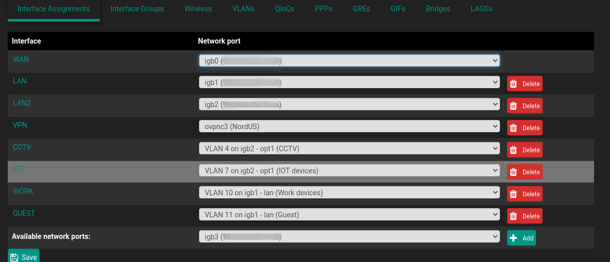
For each one of these interfaces, I have enabled the DHCP server under Services → DHCP Server

Secondly, here’s my switch config: It’s a Cisco 3750X POE+ switch.

cisco3750X#sh vlan

VLAN Name                             Status    Ports
---- -------------------------------- --------- -------------------------------
1    default                          active    Gi1/0/1, Gi1/0/2, Gi1/0/3, Gi1/0/4, Gi1/0/5, Gi1/0/6, Gi1/0/8, Gi1/0/9, Gi1/0/10, Gi1/0/11, Gi1/0/12, Gi1/0/13, Gi1/0/14, Gi1/0/15, Gi1/0/16, Gi1/0/17, Gi1/0/18
                                                Gi1/0/19, Gi1/0/20, Gi1/0/21, Gi1/0/22, Gi1/0/23, Gi1/0/24, Gi1/0/25, Gi1/0/26, Gi1/0/27, Gi1/0/28, Gi1/0/29, Gi1/0/30, Gi1/0/31, Gi1/0/32, Gi1/0/33, Gi1/0/34
                                                Gi1/0/35, Gi1/0/36, Gi1/0/37, Gi1/0/38, Gi1/0/39, Gi1/0/40, Gi1/0/41, Gi1/0/42, Gi1/0/43, Gi1/0/44
4    CCTV                             active    Gi1/0/47, Gi1/0/48
5    MAIN                             active    
6    UNUSED                           active    
7    IOT                              active    
10   WORK                             active    
11   GUEST                            active    
1002 fddi-default                     act/unsup 
1003 token-ring-default               act/unsup 
1004 fddinet-default                  act/unsup 
1005 trnet-default                    act/unsup 

Here are my trunk ports:
Port 45 carries the LAN, WORK & GUEST networks from pfSense to the switch.

cisco3750X#sh run int gi1/0/45
Building configuration...

Current configuration : 164 bytes
!
interface GigabitEthernet1/0/45
 description LAN trunk
 switchport trunk allowed vlan 1,5,10,11
 switchport trunk encapsulation dot1q
 switchport mode trunk
end

Port 46 carries the CCTV & IOT networks from pfSense to the switch

cisco3750X#sh run int gi1/0/46
Building configuration...

Current configuration : 217 bytes
!
interface GigabitEthernet1/0/46
 description LAN2 trunk
 switchport access vlan 4
 switchport trunk allowed vlan 4,7
 switchport trunk encapsulation dot1q
 switchport trunk native vlan 6
 switchport mode trunk
end

Port 7 is the trunk between the Switch and the wireless AP (TP Link EAP225)

cisco3750X#sh run int gi1/0/7 
Building configuration...

Current configuration : 173 bytes
!
interface GigabitEthernet1/0/7
 description Switch-AP trunk
 switchport trunk allowed vlan 1,4,5,7,10,11
 switchport trunk encapsulation dot1q
 switchport mode trunk
end

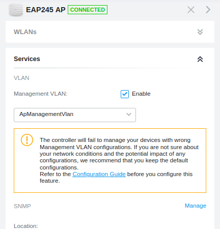
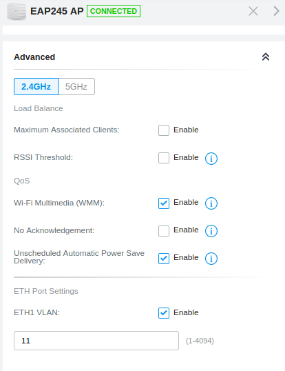
Finally on the AP I have set it up via Omada Software Controller:

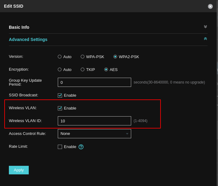
The highlighted part is the only difference between the SSID without a VLAN vs a SSID with a VLAN. I have 4 SSIDs with VLAN and 1 without.

My eventual goal is to also move my main LAN to VLAN 5 – but before that, I need to be able to get the GUEST, WORK and IOT networks working correctly.

The aim is to have the GUEST & WORK networks pretty locked down such that they can only access the internet. IOT needs internet access and also access to my media server. I haven’t set that rule up yet, I will once I get the other things working in order.

Would you please let me know what configuration am I missing that these VLANs don’t want to play ball?

Thanks in advance. Let me know if there is any additional information that you might need. Sorry for the long winded post.

Ok that’s a lot to wade through.

I have a similar setup with an EAP 245, with vlans and the Omada controller in software.

I do recall when I initially setup the AP I had issues but obviously that’s now lost to the mists of time.

However, on my network I have a management vlan that both the AP and Controller are on, I’ve used an alias for ports and included 29810:29813 for the Omada SDN v4 and 22080 for the TP-Link AP Captive Portal Port.

There is a setting for the Management vlan on the AP it defaults to 1 you might need to set this.

What I’d suggest in your situation is to the do the following:
1- setup a a management vlan
2 - setup the AP without the controller on the management vlan
3 - setup the omada controller on the management vlan then adopt the the AP

image

Actually I just saw this so perhaps while you use the Omada controller you must use a management vlan.

There I’ve set the management vlan on 11.

I would also just add I recently moved from v3 to v4 of the Omada Controller so it’s possible that the set up between the two might be slightly different. If you updated the AP to the latest firmware TP-Link says you must use v4 FYI.

This might be the mostly thoroughly documented please help me post I have ever seen. Seriously well done.

One one things missing from your documentation is your NATs. Assuming that your pfSense is the gateway if you can get out to the internet with no VLAN ID (which is actually VLAN 1) but not when you have specific a VLAN ID, then most likely you have not created any NATs for the other VLANs.

1 Like

Oh and another gotcha, if you have correctly isolated your Guest vlan they will be able to access the SSID but won’t have internet access ! You’ll need to add a rule to allow the guest network to access the Captive portal on the management vlan

I just noticed your RFC1918 rules.

I have never tried to put an RFC1918 on an inside interface before, but I am guessing that it is doing exactly what it says blocking all RFC1918 networks. Which is why you created the ICMP rules because you couldn’t ping the pfSense on that interface without it.

Thanks for your replies @neogrid & @sdfungi

@neogrid, I was hoping to just use my regular LAN as the management – as I sometimes use my laptop and at other times my desktop to get into my various services/servers/APs/routers etc. Are you saying that is not possible when using the Omada software controller to control the AP – because I was doing just that?

@sdfungi – correct, I have not set up any NAT for the vlans because I didn’t see this described anywhere. Not on the Lawrence videos nor on this pfSense vlan configuration documentation as to why they might be required. Again, note that I am not a networking pro – so it could be something that they mentioned but I might have glazed over it.

@neogrid Not quite sure what you are referring to. I haven’t set up any captive portal – neither on pfSense nor on the EAP225

@sdfungi – yes the RFC1918 rule is exactly that – it is an alias that lists all RFC1918 addresses. I was hoping to block access to everything using that and then open up specific IP above that rule using allow rules in case I wanted that particular network to be able to access a certain LAN IP
for eg. I was going to add a rule in the IOT above the RFC rule where it could access my media server.

Here’s the alias that I have defined for it:

@sdfungi, would you please point me to some documentation as to how to set up NAT for the VLANs so that I can access the internet from those SSIDs?

Thank you,

It may work on the LAN, however, I have only used the AP with vlans running on my network. The AP should also work without the controller, you can try that too.

BTW aren’t there settings for the RFC connections on the interface settings ? Perhaps I missed what you are doing.

I’m just comparing with my setup, the LAN is in place but essentially I don’t use it, everything is on vlans, so perhaps there are intermediate steps you need that are not required on my setup.

Eventually I intend to move the LAN over to VLAN5 and also move all the ports on the switch over to VLAN5. But I am not there yet.

As of now, I just need the other VLANs to work correctly and then I would look to get off of the default VLAN

I just set up some outbound NAT rules for the 4 networks and I am able to access the internet from the devices connected to those SSIDs.

I am also using a VPN to route my traffic through which is why I had set the NAT as Manual (as per their tutorial) . So I had to add the different subnets and add the appropriate Outbound NAT rules in order to be able to access the internet.

Onto some more tinkering with rules and moving the LAN off to VLAN5. I’ll get there eventually… :slight_smile:

@sdfungi Thanks for pointing me in the right direction.