I have been attempting to add a new VLAN to my SG-1100, to provide a second LAN called ‘LAN2’ with no luck. I already use the SG-1100 LAN and OPT ports for LAN and IOT (‘internet of things’) sucessfully.
I want to add my new LAN2 network to the OPT port, shared with the existing IOT network, but I have not properly undestood how the SG-1100 interal switch works and need some guidance…
So, how to do this? I have read the Netgate docs for the SG-1100 - but they chose to give a single example of configuring the SG-1100 to make the OPT port also be a member of the LAN network (both LAN and OPT ports are LAN network ports). I want two networks on the same port, which are tagged and therefore can be filtered by downstream swiches - not two ports on the same network. Irritating!
The SG-1100 contains an embedded Marvell switch that itself uses VLANs, with a single ethernet port for the system and three external ports on an embedded switch. Clever. There are pfsense menus to define the internal switch, the networks and how they are assigned to the ports on the switch:
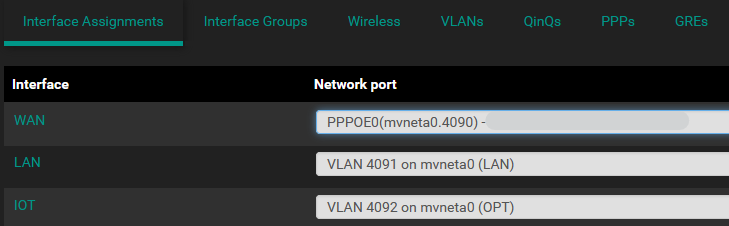
- Interfaces > Assignments
- Interfaces > Switches
Note: the Swtiches menu item only exists on Netgate hardware and is not shown on Cummunity Edition installs of pfsense.
The Switches menu page (on a SG-1100) contains only one item for the Marvel 6000 embedded switch, which itself shows up 4 ports:
- Uplink,
- WAN,
- LAN and
- OPT.
The uplink port is internal and the last 3 are the physical ports. These ports cannot be added to as they represent what the hardware provides.
There are also a number of VLANs defined with the switch, which can be altered and extended. Care must be taken or you cut yourself off. Don’t ask. Thank goodness there is a serial inteface, yes?
The VLANs are for the uplink to the single ethernet interface of the SG-1100 system (on a chip), and the three physical ports:
- Uplink with VID 1 (this is the SOC ethernet interface)
- OPT with VLAN ID 4092
- LAN with VLAN ID 4091
- WAN with VLAN ID 4090
Where I am mildly confised is the VLAN ‘members’ column, Uplink, OPT, LAN and WAN each have ‘members’ defined that I believe are the ports of the internal switch.
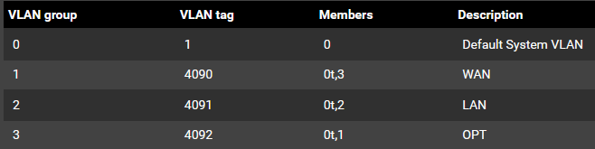
Netgate doesn’t explain what ‘members’ are, so we have to guess. This is where I am likely going wrong.
I can see that OPT has VLAN tag 4092, has members 0t and 1 that I take to mean: port 0 tagged packets, and port 1 untagged packets. Also, VLAN ID 4092 is assigned to the network interface called ‘IOT’:
I believed I need to:
- Add a new Switch VLAN (for the new network LAN2), give it a VLAN tag 4
- Set the members of the new VLAN 4 to: 0t, 1t
- Update the members of the existing VLAN 4092 to: 0t, 1t
- Assign a new network to mvneta VLAN 4, name it LAN2, enable it and then set the DHCP network range etc.
- Update my downsteam switch port connected to the SG-1100 OPT port so it expects tagged packets for IOT and LAN2…
This does not work, as my existing IOT network from the OPT port collapses. I have theories:
a) The members settings for IOT and LAN2 are wrong. This is the first thing to tackle with some feedback,
b) The downstream switch VLAN config is wrong. Likely.
Anyone care to explain the Switch VLAN member settings?
Also, am I incorrect making the assumption that I need to change from untagged packets from the OPT (for IOT) port to tagged packets (for IOT and LAN2) to they can share the single port?
I know this is TLDR, but it may help those who follow me, and I will post an update explanation when I get this figured out.
Thanks,