I have a device X 192.168.60.123 on location A and a 3rdparty server 172.16.0.2 on location C .
There is a ipsec-tunnel between location A 192.168.60.0 and location B 192.168.1.0.
Then there is a ipsec-tunnel between location B 192.168.1.0 and location C 172.16.0.0
Sending ping from B to C working. But I cannot ping from A to C ?
You’ll create a static route and not a NAT. The issue with doing it this way is now you have an extra unnecessary hop and performance loss when reaching site A to C. Also if Site B goes down then you will lose connection to site C as well. I wouldn’t recommend doing it this way.
I forgot some other necessary routes, so here is a more complete picture.
The preferred variant would be without NAT. For this to work, firstly router A needs to know how to reach router B. This connection should go through the tunnel, but it may have to be manually added as a static route (I don’t know if the IPSec setup does this automatically). Then router A needs the route to router C with router B set as the gateway. Now router B, which has a tunnel connection to C, needs a route to C (again, this may or may not be added automatically by the IPSec wizard).
To check for active routes in pfSense, go to Diagnostics → Routes.
This setup so far enables packets to travel from A to C (all this is under the premise that the firewall does not block any packets). The reverse is not true yet, though. Packets can not be returned from C to A. In order for this to work, you need three more routes: From C to B via the direct tunnel, from B to A via the direct tunnel and from C to A via B.
If you didn’t create any routes manually, then this means they were automatically created during tunnel setup.
What seems to still be missing is a route on router A that tells it where to find the network behind router C and, vice versa, a route on router C that tells it where to find the network behind router A.
This is routing 101. If a router receives a packet, it will look up the destination in its routing table in order to decide where to forward it to. It will choose the “closest” match, i.e. the match with the highest prefix. If there is no matching route otherwise, the default route (which has a prefix of 0) will catch it and the packet is sent to the default gateway.
The same is true for the reverse path. When the client in the C network responds, its response will be destined for an address in the A network. The client sends that packet to the default router (which should be router C). Therefore, router C needs to know that this packet should be sent through the tunnel to router B instead of to the default gateway.
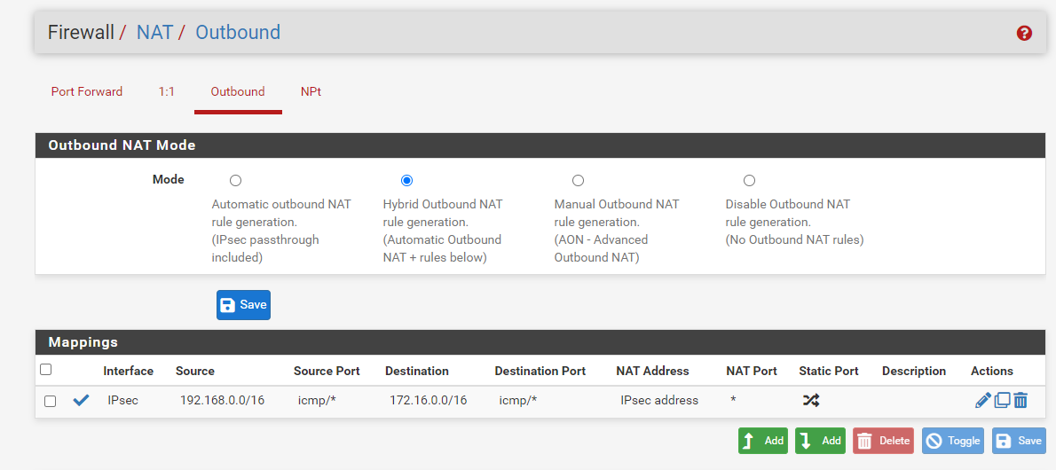
If you absolutely cannot set up a route on router C, you might be able to get away with using source NAT on router B (pfSense calls this “Outbound NAT”). Because of the tunnel, router C knows how to get to router B. By adding a source NAT rule on router B you can rewrite the source address of any packets coming from router A to the tunnel address of router B. When a client in the C network responds to such a packet, the response will be destined for router B’s tunnel address which router C knows where to find. Router B will then fix the destination address before forwarding the response to the original sender. By doing this, from any device in router C’s network, it will look like all the traffic came from router B directly. They will no longer be able to see which exact device sent a packet (in the same way a server on the internet only sees your router’s public IPv4 address).
It’s under System → Routing → Static Routes.
That is odd. Unless you are using the tunnel peer as a default gateway and since you can ping a device in the network behind router C, there should really be a route on router B that tells it how to get to the network behind router C. I’m pretty sure it should show up in the routing table even if it’s automatically configured by the tunnel setup.
Traffic is only passed between routers for so long. At some point it reaches its destination network and then it has to be sent into this network on a layer 2 link. This entry you provided basically says that for traffic destined for 192.168.1.0/24, it should go out directly on link #11 (as far as I know that’s just an arbitrary number chosen by pfSense, the table also shows the associated interface in another column).
But on router A I can only add network eg 172.16.0.0 and choose 1 gateway (the default internet gateway)
I did that, but it does not make a difference.
Then you first need to add a gateway under System → Routing → Gateways. Set the interface to the tunnel interface and the gateway to router B’s tunnel address.
Under Interfaces → Assignments → Available network ports, can you create an interface for the tunnel there? This is how it would work for OpenVPN and WireGuard interfaces. I’ve never used IPsec, but my guess is it works the same way.